The bottle program is defined
Capacity, still-water use, closure, blowing equipment and target bottle checks create the approved application basis.
Still-water preform program
Build the mold around the approved preform and required line output.
A water bottle preform mold program can be highly sensitive to preform weight, cavity consistency and useful hourly output. Its application-specific mold direction connects the approved water bottle, preform, closure, blowing process and injection platform.
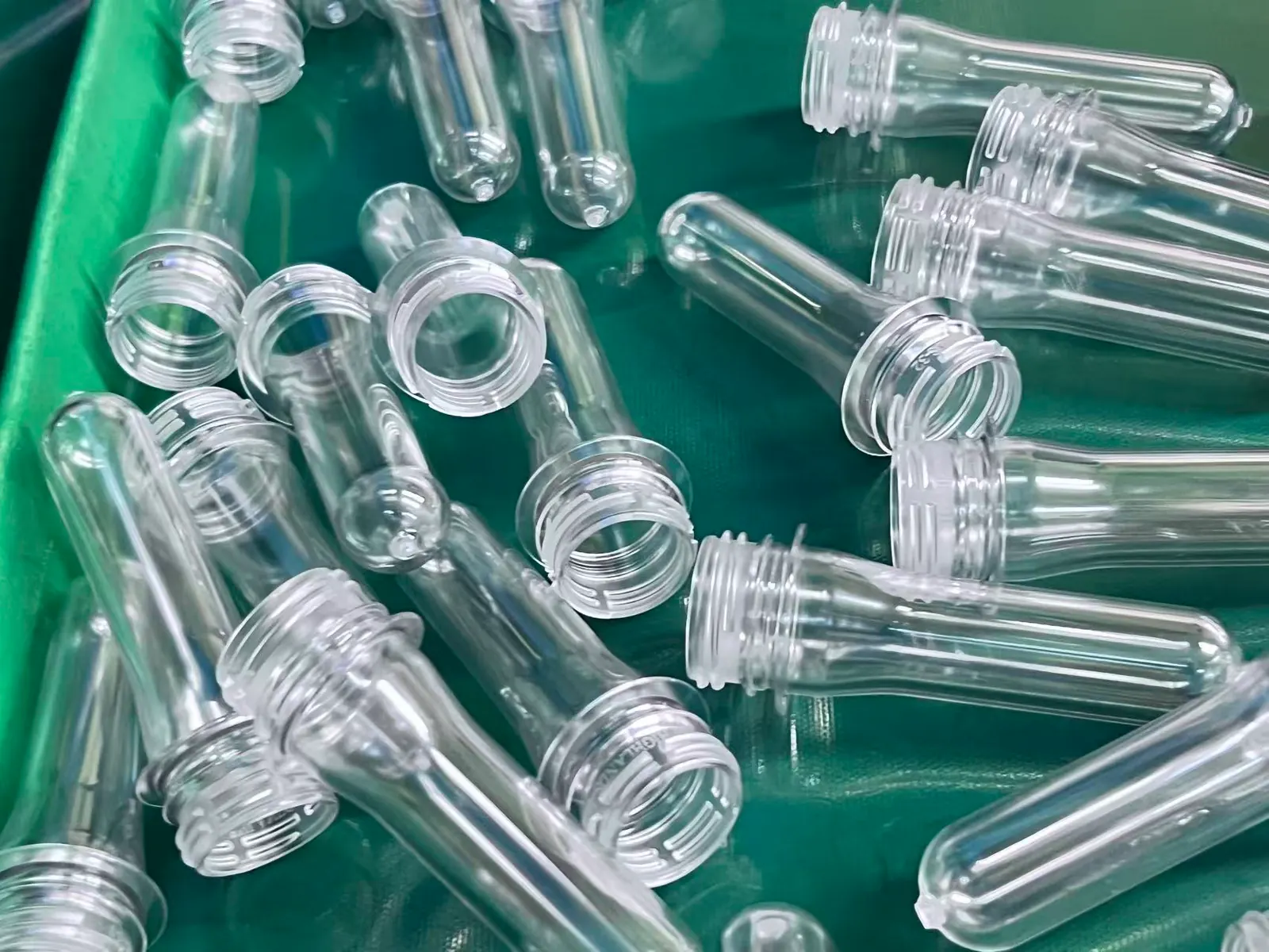
The photograph shows real PET preforms prepared for trial review. Final geometry and acceptance follow the approved water-bottle project drawings and samples.
Part basis
Approved lightweight preform
Closure
Neck and cap reviewed together
Output
Cavity selected from useful demand
Acceptance
Traceable weight and neck checks
Application fit
A strong application match exists when the filled product is water and lightweight, clarity or volume decisions drive the mold review.
Capacity, still-water use, closure, blowing equipment and target bottle checks create the approved application basis.
The approved lightweight target affects total shot, cooling, cavity direction and the sampling plan used during trial.
The project needs a justified cavity and machine combination based on saleable demand, operating hours and maintenance margin.
Part program
This application review connects the buyer's container, preform, closure, production and equipment information to a focused mold proposal. Approved drawings and samples finalize the geometry, interfaces and acceptance basis.
View imageBottle program
Bottle capacity, approved bottle drawing and still-water filling conditions
Preform
Approved preform drawing, target weight and sample status
Neck and closure
Neck-finish drawing plus the cap drawing or physical sample
PET material
Resin grade, IV basis, color and any agreed additives
Blowing process
Blowing machine, cavity count and existing process or validation basis
Output plan
Required saleable preforms per hour, shifts, downtime and growth margin
Injection platform
Exact machine model, injection unit, platen, tie bars, controls and cooling
Product-specific priorities
These priorities connect the part, cavity choice, machine fit and acceptance method to one application-specific proposal.
01
Weight reduction stays connected to the approved bottle performance and blowing window. The approved part defines the lightweight target used for the mold quotation.
02
The trial plan should identify samples by cavity and define the agreed weight, gate, appearance and molding checks instead of accepting a mixed sample bag.
03
Closure fit, thread, sealing surfaces and handling features follow the approved neck, cap and downstream handling system.
04
Cooling-water conditions, machine recovery, verified cycle and cavity count work together to establish useful bottles per hour.
Mold, cavity and machine
Water programs may justify 24, 32, 48, 64, 72 or 96 cavities when demand and the exact machine support them. Select the smallest supported option that meets confirmed saleable output with maintenance and changeover margin.
Start from the approved bottle and blowing process, then finalize preform geometry, weight, neck and resin. Control lightweight changes through the drawing and validation process so total shot, cooling and machine calculations share the same approved basis.
Water programs can make high output attractive, and the cavity count is matched to the exact injection unit, mold envelope, hot-runner controls, cooling supply and plant maintenance plan. Compare neighboring cavity options using one part and one operating basis.
Define which samples are identified by cavity, how weight and selected dimensions are checked, which visual and gate conditions matter and whether downstream blowing samples are included. Approved project documents provide the acceptance values for a clear and repeatable trial.
Water programs may justify 24, 32, 48, 64, 72 or 96 cavities when demand and the exact machine support them. Select the smallest supported option that meets confirmed saleable output with maintenance and changeover margin.
Compare Cavity OptionsTotal part shot from approved weight and selected cavities
Plasticizing and recovery at the verified production cycle
Mold envelope, opening, take-out and preform handling
Cooling capacity and hot-runner control interfaces
| Decision factor | What to check | Why it changes the project |
|---|---|---|
| Bottle program | Capacity, still-water use, blowing line, bottle drawing and required tests | Connects the mold to the approved downstream bottle rather than a generic application label. |
| Preform definition | Drawing revision, resin, target weight, wall distribution and neck finish | Defines the molded part and the basis for shot, cavity and trial comparison. |
| Closure system | Neck standard, cap drawing or sample, tamper band and sealing interface | Prevents a familiar diameter name from being mistaken for a fully confirmed neck. |
| Capacity direction | Required output, operating hours, cavity range and exact machine | Balances high-volume demand with realistic machine, runner, cooling and maintenance capability. |
| Acceptance evidence | Weight, selected dimensions, neck and gate condition, visual review and traceable cavity samples | Turns lightweight and consistency requirements into an executable project trial plan. |
Trial and acceptance
The sample plan follows the approved part and application. Traceable samples, recorded test conditions and agreed inspection methods turn life, cycle and quality goals into a clear acceptance path.
Verify a complete cavity set under the agreed machine, resin and cooling conditions.
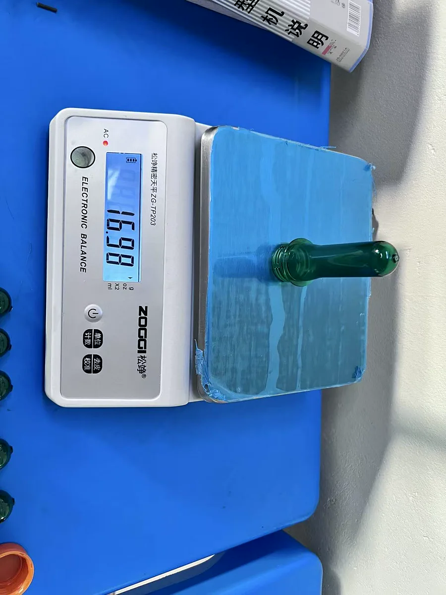
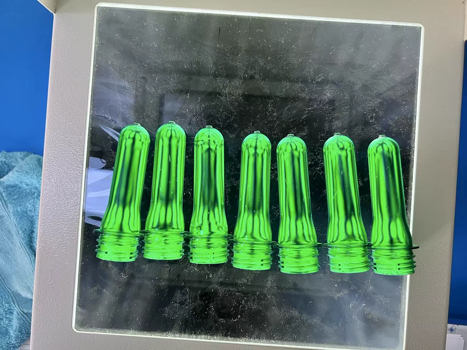
Supply cavity-identified samples for the agreed weight, neck, gate and visual checks.
Check the approved cap and any agreed transfer-ring or downstream handling requirement.
If blowing or bottle tests are included, state the machine, bottle checks and acceptance responsibility before trial.
 View image
 View image
Connect the target weight to the approved bottle design, blowing process and validation basis.
Match the high-volume target to an injection platform that supports the selected mold.
Source-confirmed water preforms, bottles and trial records support the application-specific proposal.
Application RFQ
Send the water bottle and preform basis first. If weight or cavity remains open, ask for a comparison rather than treating an estimate as approved.
What happens next
Buyer questions
The answers define the decision method. Exact material, performance, cavity and acceptance values remain tied to the approved project.
Provide the bottle and preform drawings, water application, capacity, resin, target weight, neck and cap, blowing process, output target, injection machine and trial evidence requirements.
The exact part, total shot, mold envelope, runner, cooling, controls, machine and maintenance plan identify the supported high-cavity option.
Use a traceable cavity sample plan and project-approved weight and dimensional criteria under recorded trial conditions. Include gate and visual review where relevant.
Use source-confirmed water preforms and finished bottles, the approved drawing, trial samples with cavity traceability and the assigned responsibility for downstream blowing or bottle validation.
Next decision
Core decision
PET Preform Mold for Bottle ProductionCore decision
PET Preform Mold ApplicationsApplication decision
Beverage Bottle Preform MoldTechnical decision
PET Preform Mold Neck Finish OptionsCore decision
PET Preform Mold Cavity OptionsTechnical decision
Mold Compatibility with PET Preform Injection MachinesCore decision
PET Preform Mold Quotation