24 cavities leaves little margin
The 24-cavity calculation depends on excessive utilization or operating hours, while 32 creates useful production margin at the same verified cycle.
32 cavity production review
Use 32 cavities as the balanced production step between 24 and 48.
A 32-cavity mold is the controlled middle production step when the extra eight cavities create useful capacity, fit the exact injection machine and make a direct move to a 48-cavity system unnecessary.
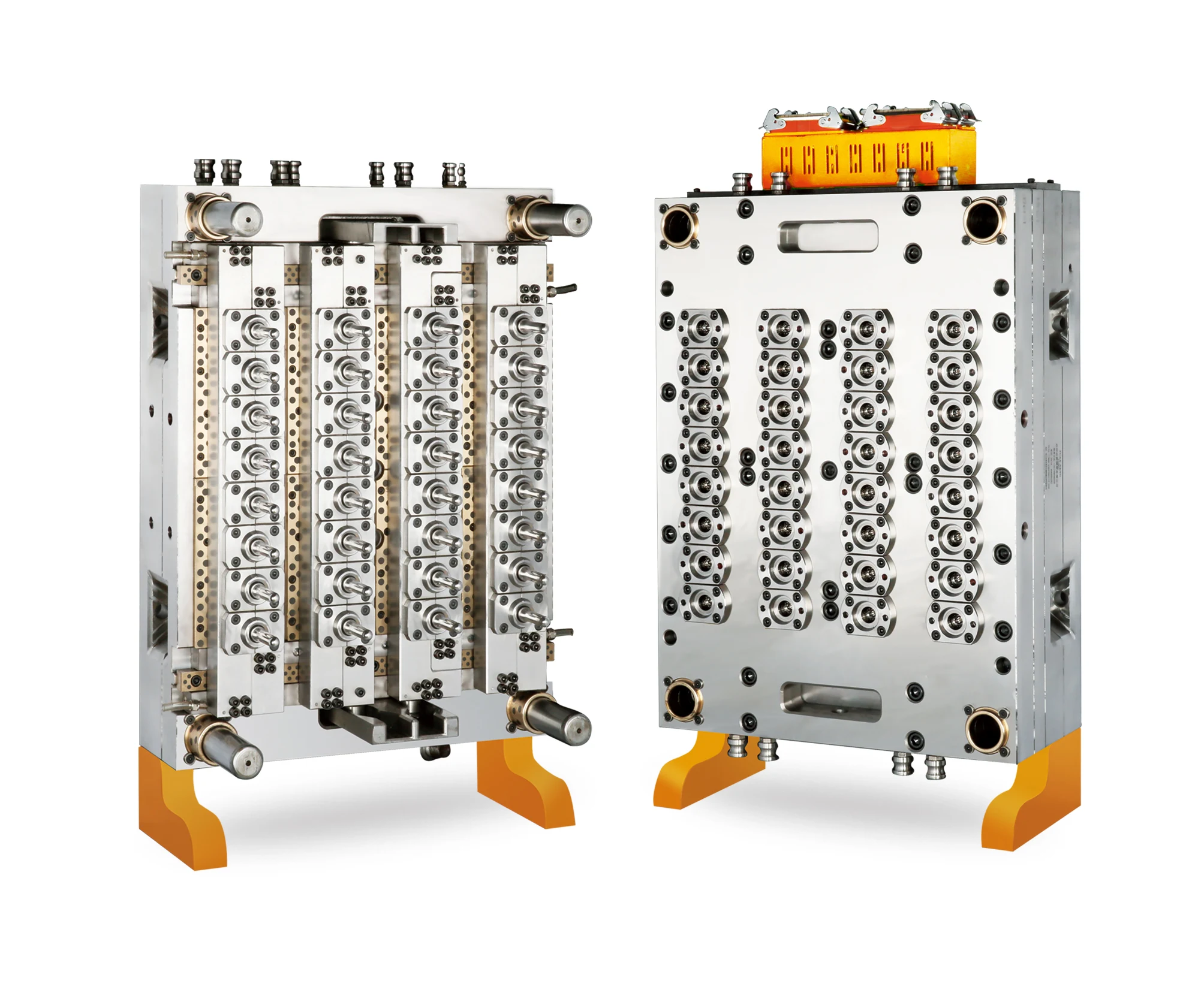
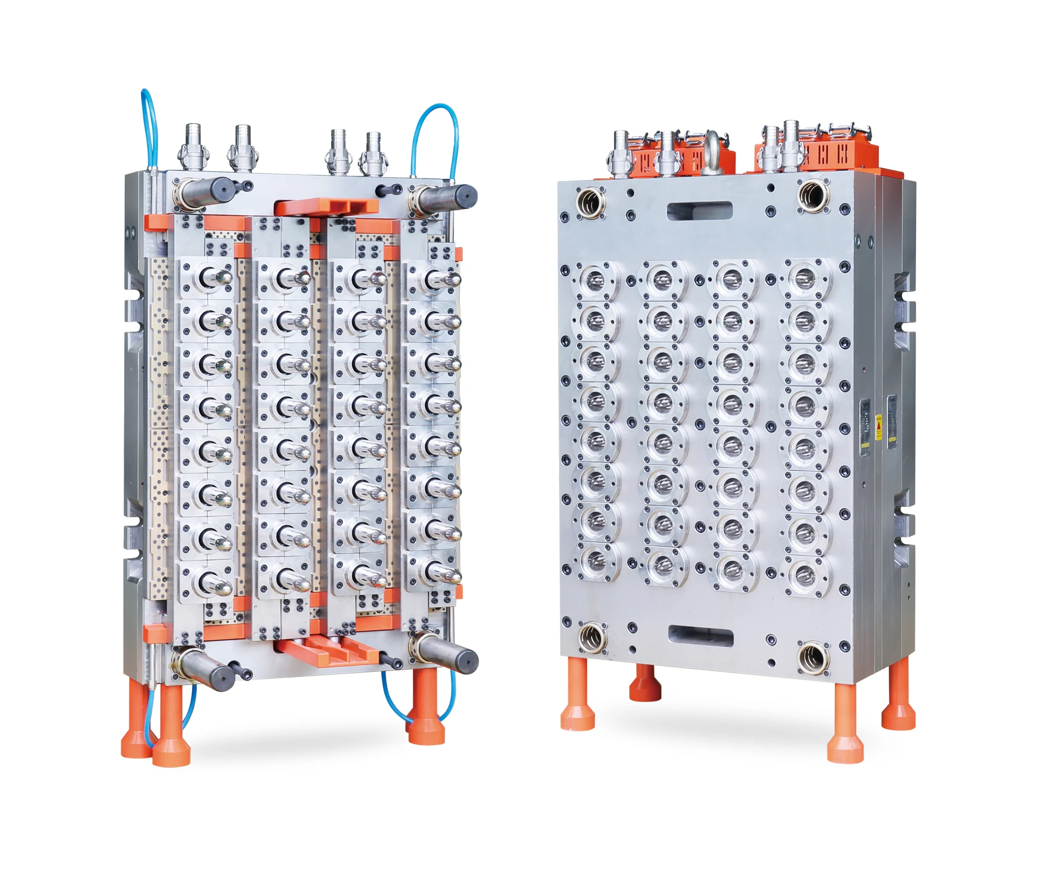
A 4 x 8, 32-cavity PET preform mold reference is shown. Final neck finish, preform weight, mold envelope, runner layout and machine interface follow the approved project drawing.
Cavity count
32 cavities
Output step
+33.3% vs 24 per cycle
Selection basis
Required useful output
Machine fit
Exact model review
Cavity selection
Use 32 cavities when it creates useful margin over 24 without adding capacity, machine demand or maintenance responsibility that the plant cannot use.
+33.3%
parts per cycle versus 24 cavities
A mathematical capacity relationship, not a promised production cycle.
The 24-cavity calculation depends on excessive utilization or operating hours, while 32 creates useful production margin at the same verified cycle.
Confirmed demand is well served by 32 cavities when this option meets the output target while keeping the machine, controls and maintenance plan efficient.
Total shot, plasticizing, platen, tie bars, mold height, opening, controller, cooling and take-out all support the proposed 32-cavity mold.
Product definition
The approved neck finish, weight, resin and application define the shot, stack geometry, cooling demand and acceptance method for the 32-cavity product.
 View image
Mold output
32 PET preforms per completed molding cycle
Output relationship
33.3% more parts per cycle than 24; 33.3% fewer than 48
Representative use
Water, beverage and other drawing-defined PET preform programs
Neck finish
Selected from the approved preform and closure drawing
Preform weight
Defined by the approved part drawing and used in the 32-cavity shot calculation
PET material
Resin grade, color and additives supplied with the project data
Cavity layout
4 x 8 is shown in the reference; final layout follows the project drawing
Useful output
Calculated from a verified cycle and the buyer's operating plan
Available neck program
The available neck program supports common bottle projects. Each mold is configured to the approved neck and closure drawing for the specific project.
Mold construction
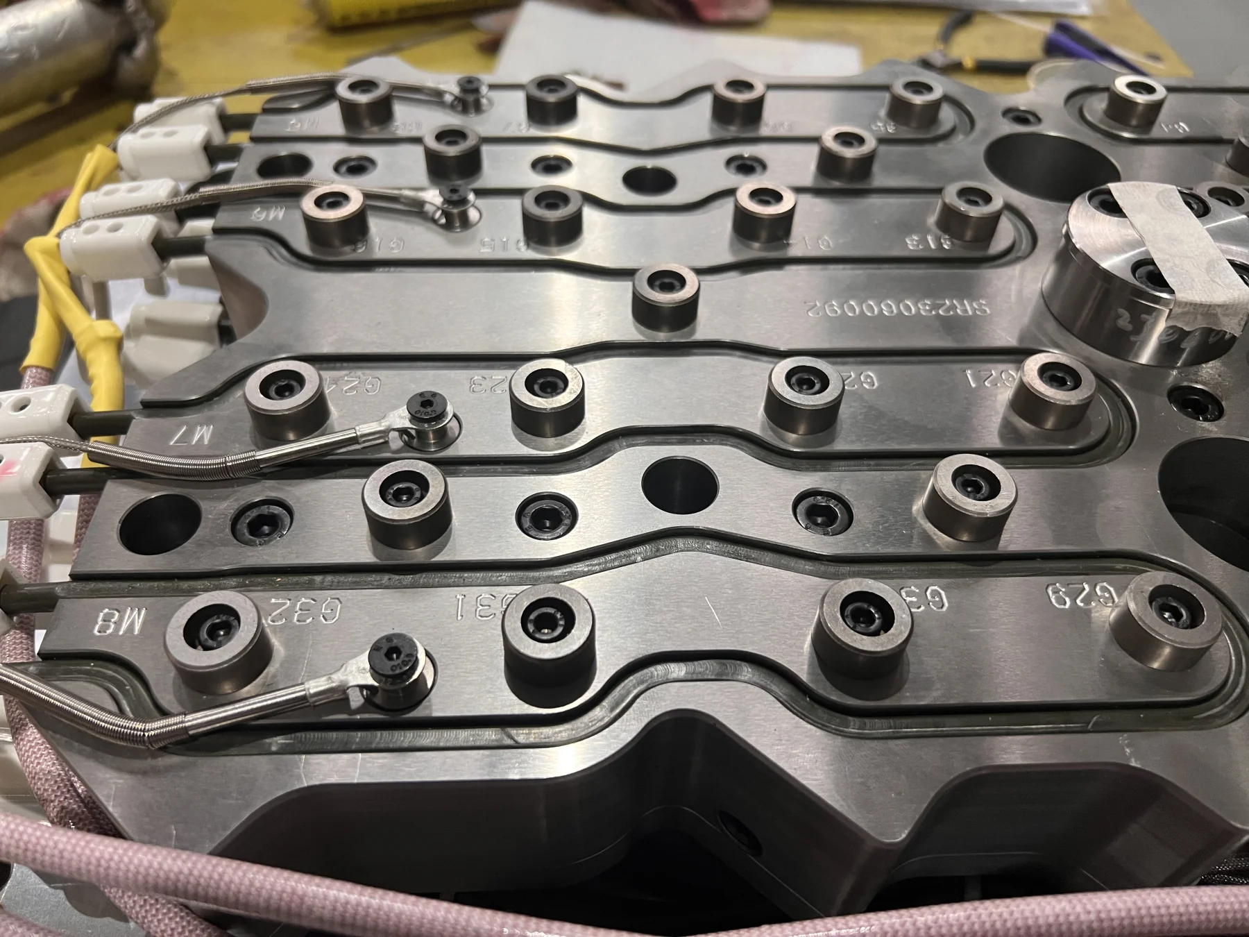
Record the material, heat treatment, alignment, cooling and 32-drop hot-runner scope used for the approved preform and machine.
View imageMold base
420 stainless steel
Core, cavity and neck ring
M333, hardened to HRC 48-51
Heat treatment
German Ipsen equipment
Hot-runner components
German HOTSET heaters with PCT nozzles and insulators
01
Available basis
The available material basis uses a 420 stainless-steel mold base with M333 cores, cavities and neck rings hardened to HRC 48-51, with heat treatment using German Ipsen equipment.
Project specification
The quotation and approved drawing record the final material schedule, lock-ring material and selected surface treatment.
02
Available basis
Taper matching between the core and lock ring, together with a double-taper neck-ring structure, is an available design approach for alignment and service replacement.
Project specification
The approved mold drawing identifies the selected alignment, replaceable inserts and component numbering method.
03
Available basis
Spiral independent cavity-water circuits are an available cooling approach for controlling heat removal across the 32-cavity set.
Project specification
The final circuit map is matched to the plant's water temperature, pressure and flow.
04
Available basis
The available hot-runner component package uses HOTSET heaters with PCT nozzles and insulators. The 32-drop architecture is designed around the approved preform.
Project specification
Define runner type, valve-gate actuation, heating zones, controller, connectors, wiring map and service parts in the proposal.
 View image
Machine and output
The capacity calculation identifies the smallest standard cavity count that meets the entered output at a verified cycle. The machine review then matches shot capacity, platen, mold height, controls, cooling and take-out.
32 x approved preform weight, process allowance, screw diameter, pressure and plasticizing capacity
Platen size, tie-bar spacing, mold height range, mounting pattern and proposed mold drawing
Opening stroke, daylight, ejector or take-out clearance and mold handling method
Temperature zones, connectors, controller capacity and valve-gate actuation
Cooling-water temperature, pressure and flow plus air, hydraulic and electrical interfaces
Approved preform, PET resin, verified cycle, required output, operating hours and downtime margin
Cavity feasibility
Cavity comparison
Enter weight and output
The result will show the cycle ceiling and part mass for 24, 32, 48, 64, 72 and 96 cavities. A specific recommendation appears only when a verified cycle is entered.
The comparison uses preform weight for part mass and a verified cycle for output selection. Wall thickness, geometry, PET resin, cooling water, hot runner, machine performance and quality requirements complete the engineering review.
24 versus 32 versus 48
Keep the preform, verified cycle, operating plan and machine basis identical so the 24-, 32- and 48-cavity options can be compared on equal terms.
| Decision factor | 24 cavities | 32 cavities | 48 cavities | What to decide |
|---|---|---|---|---|
| Parts per cycle | 24 preforms | 32 preforms | 48 preforms | 32 adds eight parts over 24; 48 adds sixteen over 32 at the same cycle. |
| Part shot basis | 24 x approved weight | 32 x approved weight | 48 x approved weight | Add the same project process allowance and verify each option against the exact injection unit. |
| Capacity role | Controlled lower step | Middle production step | Higher-output step | Select the smallest supported option that meets confirmed demand with operating margin. |
| Runner and controls | 24-drop system | 32-drop system | 48-drop system | Compare zones, actuation, connectors, spares and service access on one technical basis. |
| Selection trigger | Already meets demand | Closes a proven 24-cavity gap | Growth can use the extra capacity | Choose the middle option when the demand and machine calculation show measurable operating value. |
Trial and acceptance
The acceptance plan connects the approved part to the exact trial machine and conditions, with every sample traceable to its cavity position.
01
Approve the preform drawing, neck finish, weight, PET grade and visible quality requirements.
02
Close shot, platen, tie-bar, mold-height, opening, control, utility and take-out checks before final design.
03
Run on the agreed machine with the agreed PET resin and record cooling, process settings and the verified cycle.
04
Verify normal molding from all cavities and supply a complete cavity-identified 32-piece sample set for the agreed checks.
05
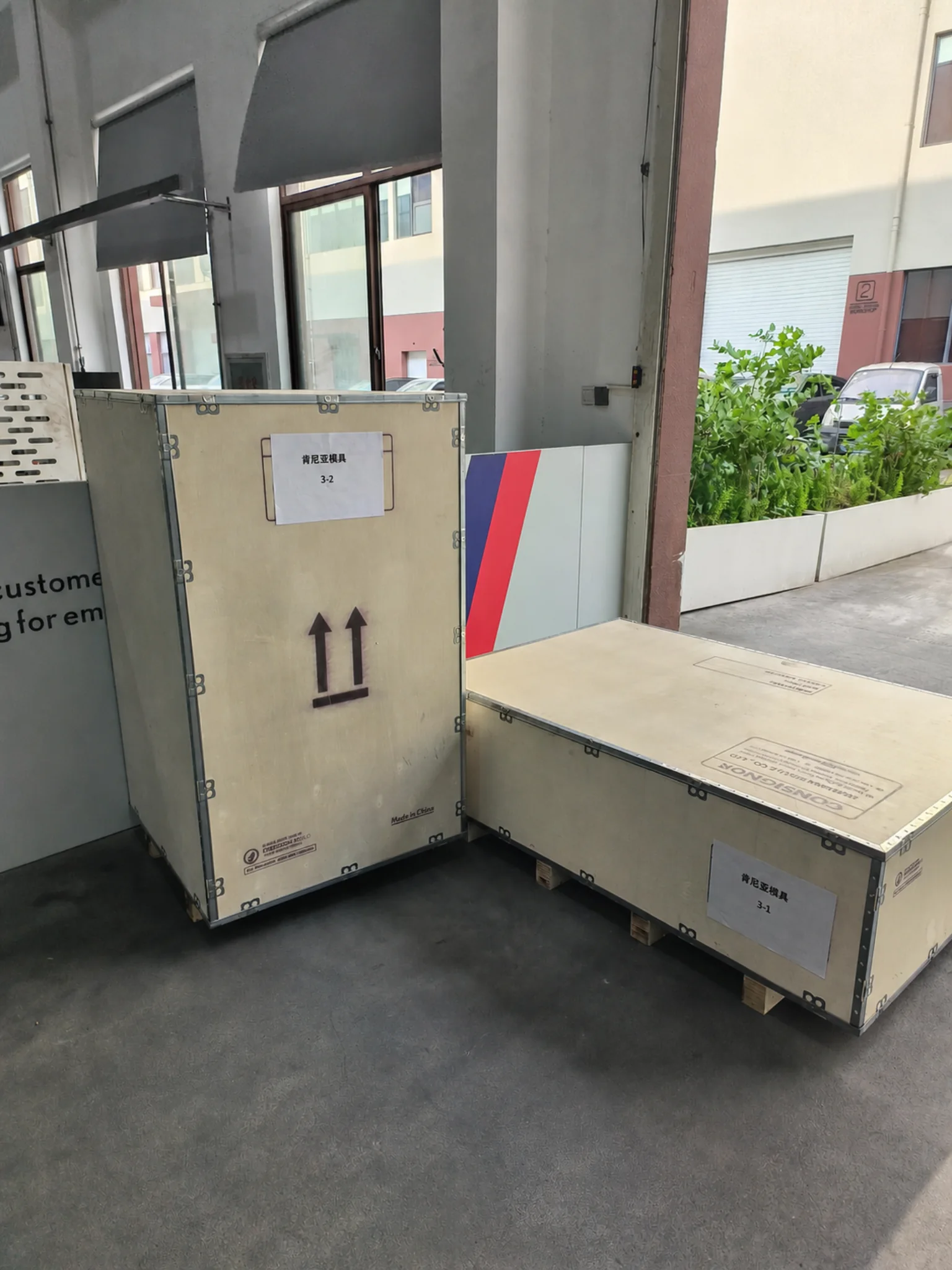
Provide trial video and inspection records, close corrective actions, then verify documents, spares, rust prevention and export packing.
Inspection evidence
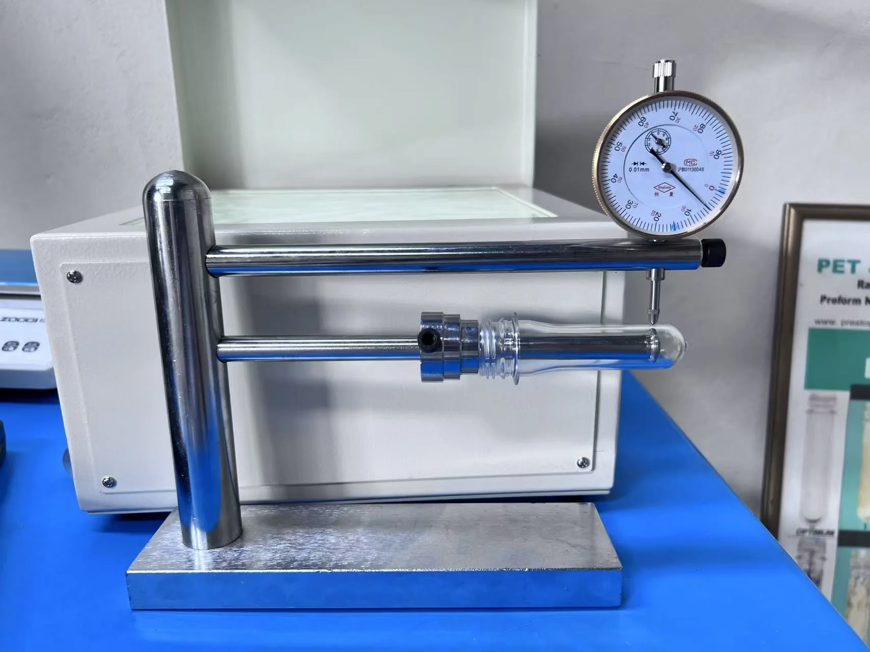
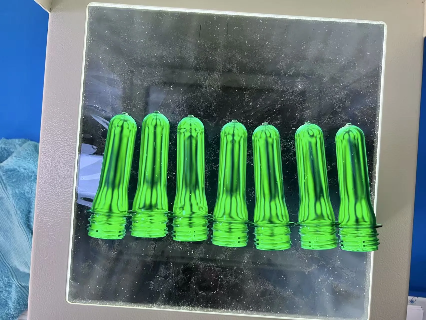
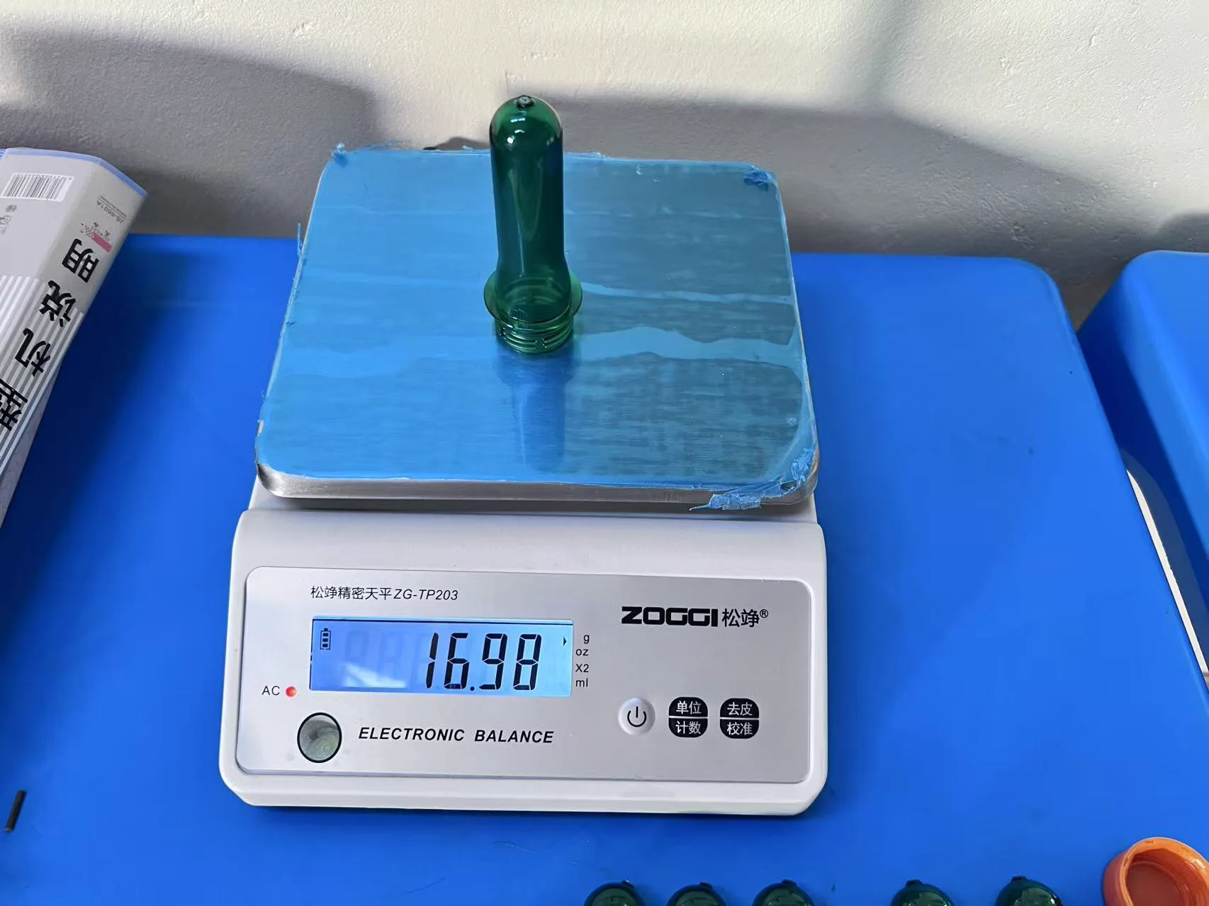
These practical inspection references show how final records capture the approved preform, trial condition, measured feature, method and cavity identification.
 View image
 View image
 View image
The quotation fixes exact quantities from the project-specific spare-parts set.
 View image
Enough to begin the review
32-cavity RFQ
A drawing or clear sample, required output and exact machine model provide a useful starting point for the first technical review.
What happens next
Buyer questions
The answers explain the selection method. Exact values remain tied to the approved part, machine and trial conditions.
Choose 32 when the additional eight preforms per cycle create useful production margin and the exact machine supports the added shot, mold envelope, controls and cooling without an unnecessary platform change.
At the same verified cycle and operating condition, 32 cavities produces 33.3% more parts per cycle than 24. Real useful output still depends on downtime, rejects, changeovers and the verified process cycle.
Compare them when forecast demand may outgrow 32, when both options fit the supported machine platform, or when 32 inherits most of the 48-cavity control and maintenance burden. Keep the part, cycle and operating assumptions identical.
Yes, when both proposed mold drawings match the machine's total shot, plasticizing, tie-bar spacing, platen, mold height, opening, controller zones, cooling, valve-gate actuation and take-out capacity.
The available program includes PCO 1881, PCO 1810, 29/25 and 30/25, with other finishes reviewed from the approved preform and closure drawing. Each mold uses the agreed finish, with interchangeability included when specifically designed into the project.
Request the recorded trial basis, a complete cavity-identified 32-piece sample set, agreed neck, weight, gate and appearance checks, trial video, basic inspection records and closure of any failed acceptance point before packing.