The oil bottle is approved or under controlled development
Capacity, geometry, grip or handle concept, blowing process and relevant transport checks are documented.
Edible-oil packaging program
Calculate the heavier preform, closure and bottle geometry before selecting cavities.
An oil bottle preform mold program can involve more part mass and different bottle, grip, closure and distribution requirements than a lightweight water program. Those application-specific differences change shot, cooling, cavity feasibility and machine demand.
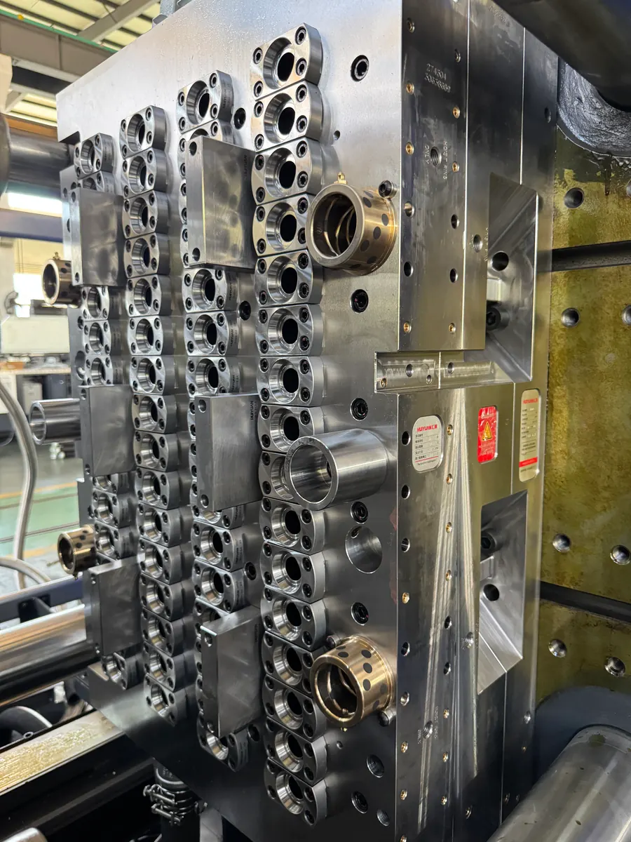
The photograph shows a real PET preform mold cavity side installed for machine review. The approved oil preform, closure and bottle program define the final stack and cavity layout.
Part mass
Often heavier than water
Bottle form
Grip or handle if applicable
Closure
Leak and cap compatibility
Cavity
Recalculated from shot and output
Application fit
A strong application match exists when oil-bottle weight, geometry, closure or handling conditions make a water-bottle assumption unreliable.
Capacity, geometry, grip or handle concept, blowing process and relevant transport checks are documented.
Total shot, cooling and realistic cavity count need to be recalculated from the actual drawing and resin.
The neck, cap, sealing and tamper interfaces are confirmed together before mold components are finalized.
Part program
This application review connects the buyer's container, preform, closure, production and equipment information to a focused mold proposal. Approved drawings and samples finalize the geometry, interfaces and acceptance basis.
View imageOil bottle
Approved capacity, bottle drawing, grip or handle concept and distribution condition
Preform
Approved drawing, weight, wall distribution, resin and color
Neck and cap
Closure drawing or sample, sealing surfaces and tamper-evidence requirements
Handle method
Integrated geometry, inserted handle or no handle, if relevant to the bottle
Blowing process
Machine, mold and the bottle-validation method for the oil program
Output
Required saleable preforms per hour and realistic shifts
Injection machine
Exact unit, plasticizing, envelope, controls, cooling and handling
Product-specific priorities
These priorities connect the part, cavity choice, machine fit and acceptance method to one application-specific proposal.
01
Calculate approved preform weight multiplied by cavities before carrying a water-program cavity count into the oil project.
02
Bottle handling geometry may affect the bottle and blowing process independently of the injection-molded neck. State the responsible design method.
03
The approved cap, seal, tamper band and transport condition should be available before the neck stack and acceptance plan are frozen.
04
If filled-bottle leakage, drop, stacking or distribution checks are required, state who performs them and which sample or standard controls acceptance.
Mold, cavity and machine
Select the oil-preform cavity count from the approved weight, verified cycle, required output and the exact machine's shot, plasticizing and cooling capacity, then compare neighboring options on the same basis.
Calculate total shot from the approved preform weight for every candidate cavity count, then review injection capacity, plasticizing, mold envelope, cooling and opening. This establishes the supported cavity count for the heavier oil preform on the selected machine.
Grip, handle and bottle geometry questions usually belong to the bottle and blowing program, but they can influence preform weight and distribution. Record who approves the bottle design and how any resulting preform revision changes the mold quotation.
Provide the approved cap drawing or controlled sample with the neck data. Review sealing and tamper interfaces and downstream equipment. The mold quotation records the neck definition used before core and neck-ring production begins.
Select the oil-preform cavity count from the approved weight, verified cycle, required output and the exact machine's shot, plasticizing and cooling capacity, then compare neighboring options on the same basis.
Compare Cavity OptionsHeavier total part shot and process allowance
Plasticizing recovery and cooling demand
Mold envelope, preform take-out and handling
Blowing, handle and bottle-validation boundary
| Decision factor | What to check | Why it changes the project |
|---|---|---|
| Bottle geometry | Capacity, shape, grip or handle approach, blowing line and transport conditions | Provides the downstream basis for preform geometry and weight. |
| Preform shot | Approved weight, resin, wall distribution and total shot for each cavity option | Determines injection-unit and plasticizing demand and can limit cavity count. |
| Neck and cap | Thread, support ring, seal, tamper interface and closure samples or drawings | Creates a controlled sealing and filling-line interface for the oil bottle. |
| Cavity realism | Demand, operating hours, machine, cooling and mold envelope for neighboring counts | Balances heavier-part production with a supportable platform instead of chasing a water-project number. |
| Trial and bottle samples | Preform checks, traceable cavities, downstream blowing and agreed bottle validation responsibility | Connects mold acceptance to the actual oil packaging program. |
Trial and acceptance
The sample plan follows the approved part and application. Traceable samples, recorded test conditions and agreed inspection methods turn life, cycle and quality goals into a clear acceptance path.
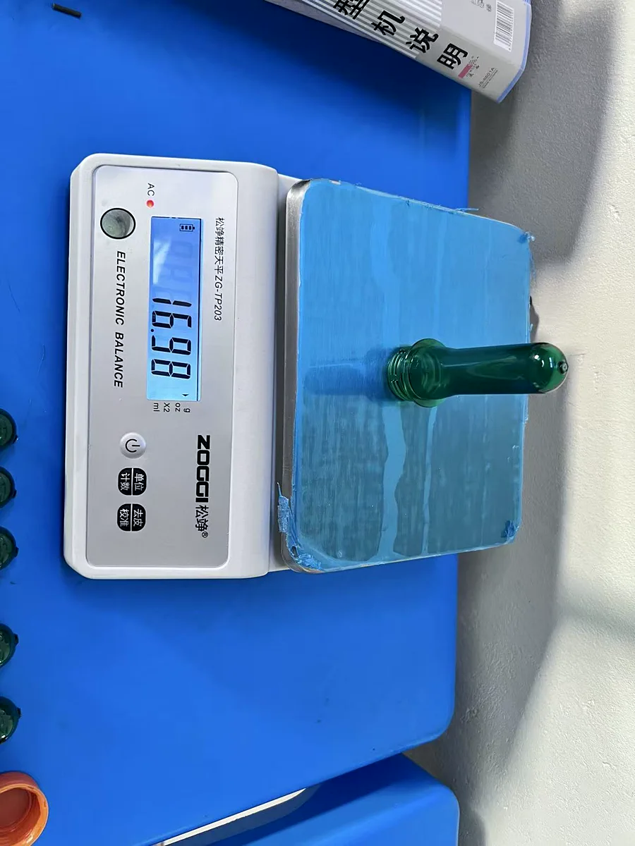
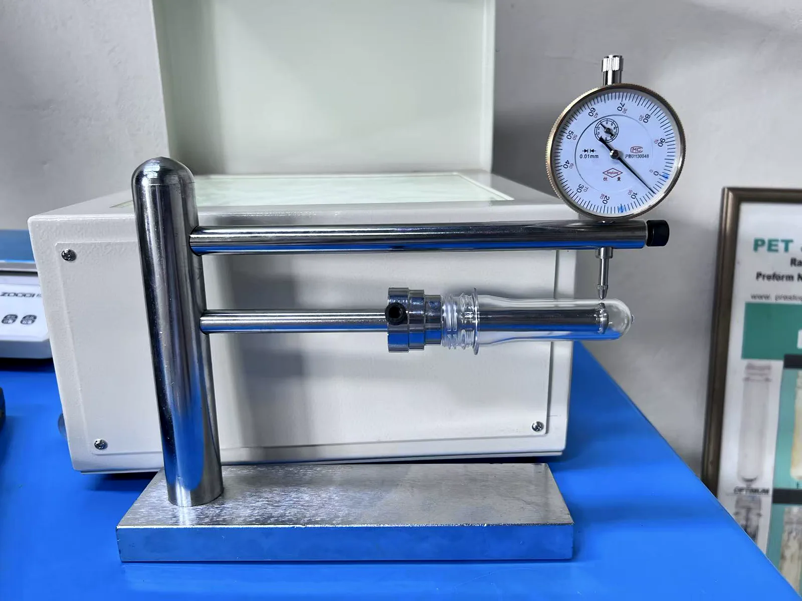
Use traceable cavity samples against the approved oil-preform and closure drawings.
Inspect molding, gate and visual conditions under the recorded machine, resin and cooling basis.
State whether cap fit or bottle leak testing is included and identify the responsible party.
When required, link blow, fill, drop, stacking or distribution tests to the approved bottle program.
 View image
 View image
Higher part weight can exceed shot, cooling or machine assumptions.
Bottle redesign can change preform weight and invalidate the approved mold basis.
Neck and closure mismatches should be removed through drawings and samples before production.
Application RFQ
Send the oil bottle, preform and cap as one requirement package. Ask the supplier to show how heavy-part shot and cooling affect cavity and machine options.
What happens next
Buyer questions
The answers define the decision method. Exact material, performance, cavity and acceptance values remain tied to the approved project.
A heavier or larger preform increases total shot, plasticizing and cooling demand and may require a larger mold envelope or machine. Calculate the exact effect from the approved part.
The handle or grip is mainly a bottle and blowing-program decision, but resulting bottle geometry can change the approved preform weight or distribution. Control those revisions before mold production.
Provide the neck and cap drawings or controlled samples, including sealing and tamper features, plus relevant downstream capping-line information.
Use oil preforms, caps and finished bottles tied to the proposed scope, together with construction photographs, approved drawings and the agreed bottle-validation plan.
Next decision
Core decision
PET Preform Mold for Bottle ProductionCore decision
PET Preform Mold ApplicationsApplication decision
PET Jar and Wide Mouth Preform MoldTechnical decision
PET Preform Mold Neck Finish OptionsCore decision
PET Preform Mold Cavity OptionsTechnical decision
Mold Compatibility with PET Preform Injection MachinesCore decision
PET Preform Mold Quotation