Moderate confirmed demand
Required saleable output can be met with realistic operating hours and a stated project cycle assumption without relying on continuous perfect utilization.
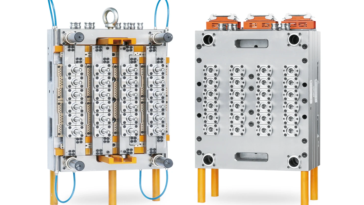
24 cavity water preform program
Define the preform, machine and useful output before the mold price.
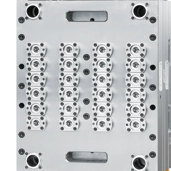
This page shows the product details behind a 24-cavity water bottle preform mold. The final configuration is built from the approved preform drawing, the exact injection machine and an agreed trial and acceptance plan.
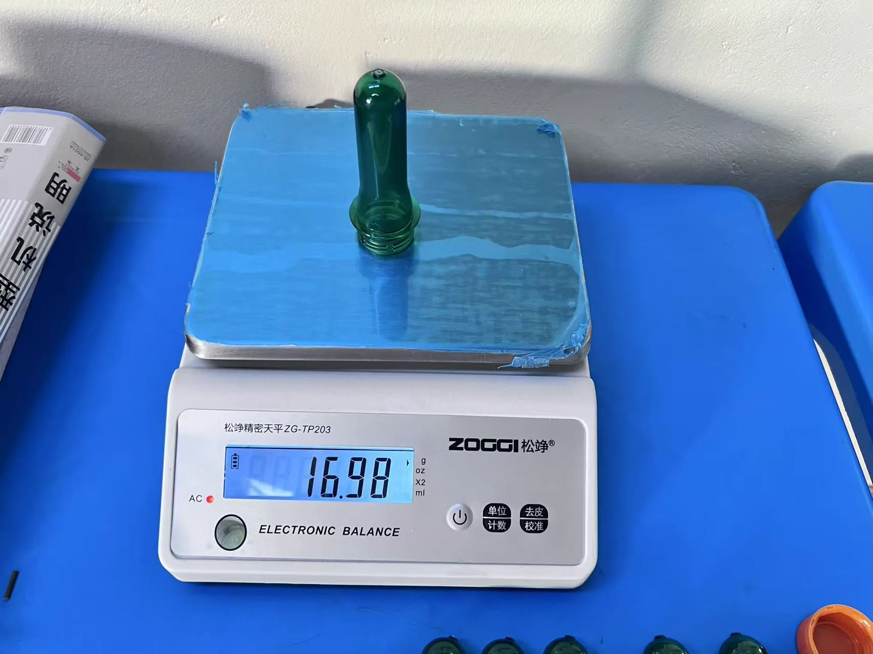
A 24-cavity, 28 mm / 38 g mold reference is shown. Final neck finish, preform weight, mold envelope and machine interface follow the approved project drawing.
Cavity count
24 cavities
Representative application
Water bottle preforms
Neck and weight
Approved drawing
Machine fit
Exact model review
Cavity selection
Shortlist 24 cavities when the demand case and plant resources favor a controlled production step.
Required saleable output can be met with realistic operating hours and a stated project cycle assumption without relying on continuous perfect utilization.
The buyer prefers to keep mold, machine, controller, spares and maintenance complexity aligned with current demand rather than pay for unused capacity.
The plant wants fewer cavities and runner components to inspect, service and stock while the product program is still developing.
Product photo index
Select a photograph to jump to its technical context. Each full-size image can also be opened for closer inspection.
Product definition
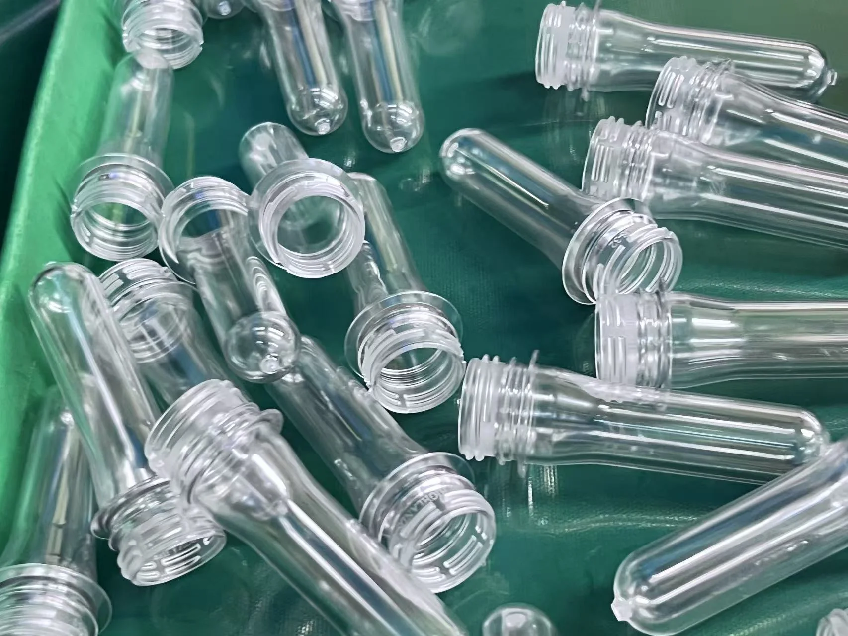
Cavity count is only one line of the specification. The approved water-bottle preform defines the neck, weight, resin, cooling demand, shot requirement and acceptance method.
 View image
Mold output
24 PET preforms per completed molding cycle
Representative use
Water bottle preforms
Neck finish
Selected from the approved preform and closure drawing
Preform weight
Defined by the approved part drawing and used in the 24-cavity shot calculation
PET material
Resin grade, color and additives supplied with the project data
Cavity layout
Confirmed on the project mold drawing
Injection machine
Checked against the exact brand, model and injection unit
Useful output
Calculated from verified cycle time, utilization and operating hours
Available neck program
This list shows the available supplier program. Each mold follows one approved neck drawing, with interchangeability included when it is designed and agreed in the project scope.
Mold construction
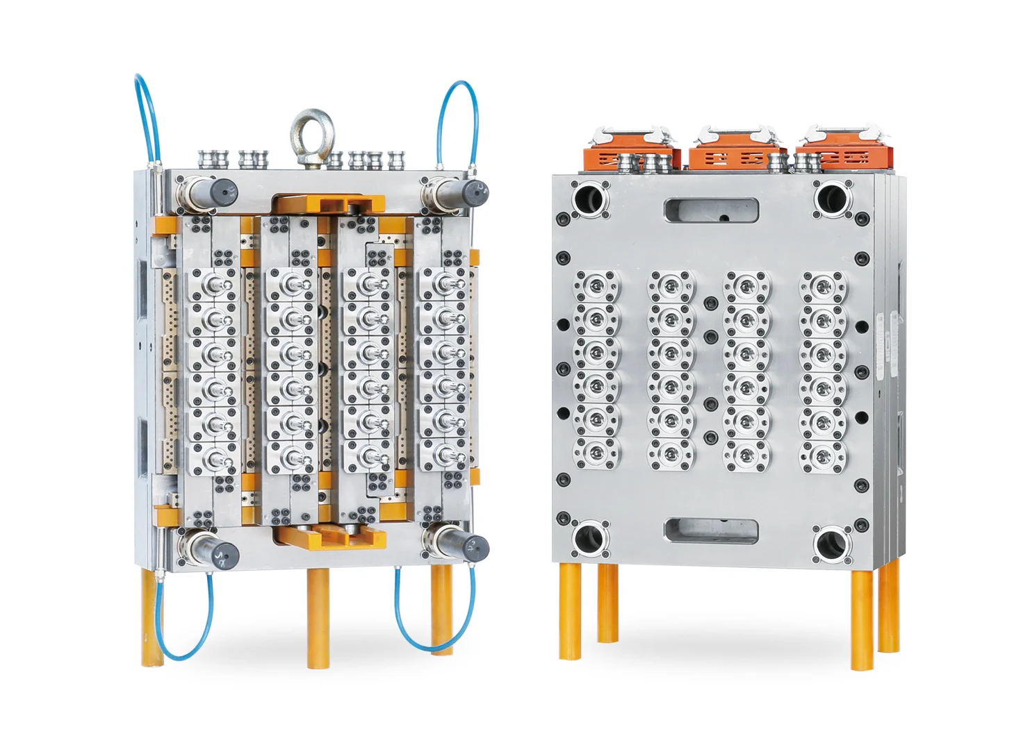
The 24-cavity specification records the material, alignment, cooling and runner design used for the approved preform and injection machine.
 View image
Available design option
The 24-cavity material schedule uses a 420 stainless-steel mold base and M333 cores, cavities and neck rings hardened to HRC 48-51. Heat treatment is performed using German Ipsen equipment.
Project specification
The approved mold drawing records the lock-ring material, surface treatment and final material schedule for the selected preform.
Available design option
Taper matching between the core and lock ring, together with a double-taper neck-ring structure, is an available design approach.
Project specification
The approved mold drawing records the selected alignment and replaceable-component structure.
Available design option
Spiral independent cavity-water circuits are an available cooling approach for controlling heat removal at each cavity.
Project specification
The circuit layout is matched to the project's water temperature, pressure and flow.
Available design option
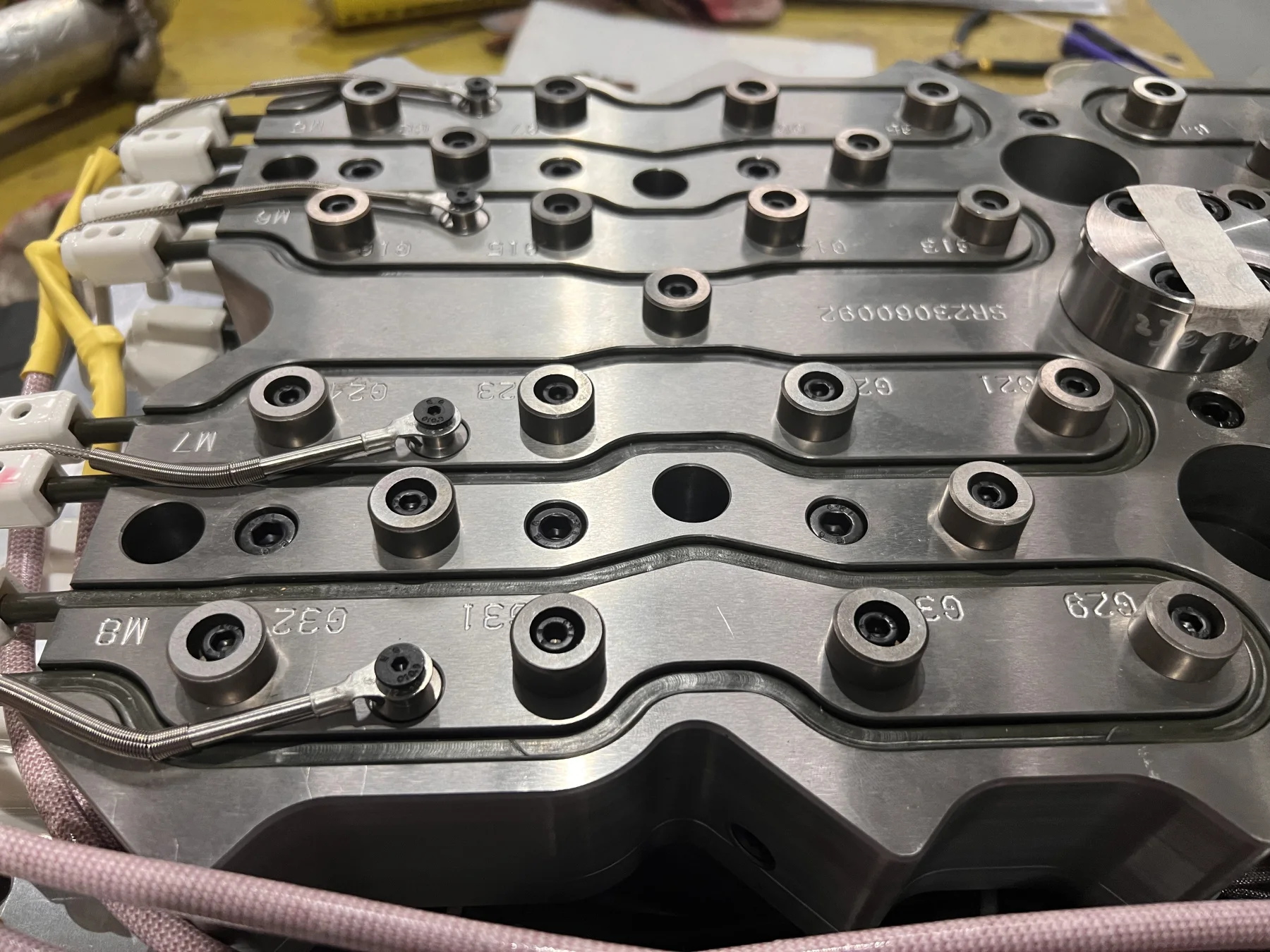
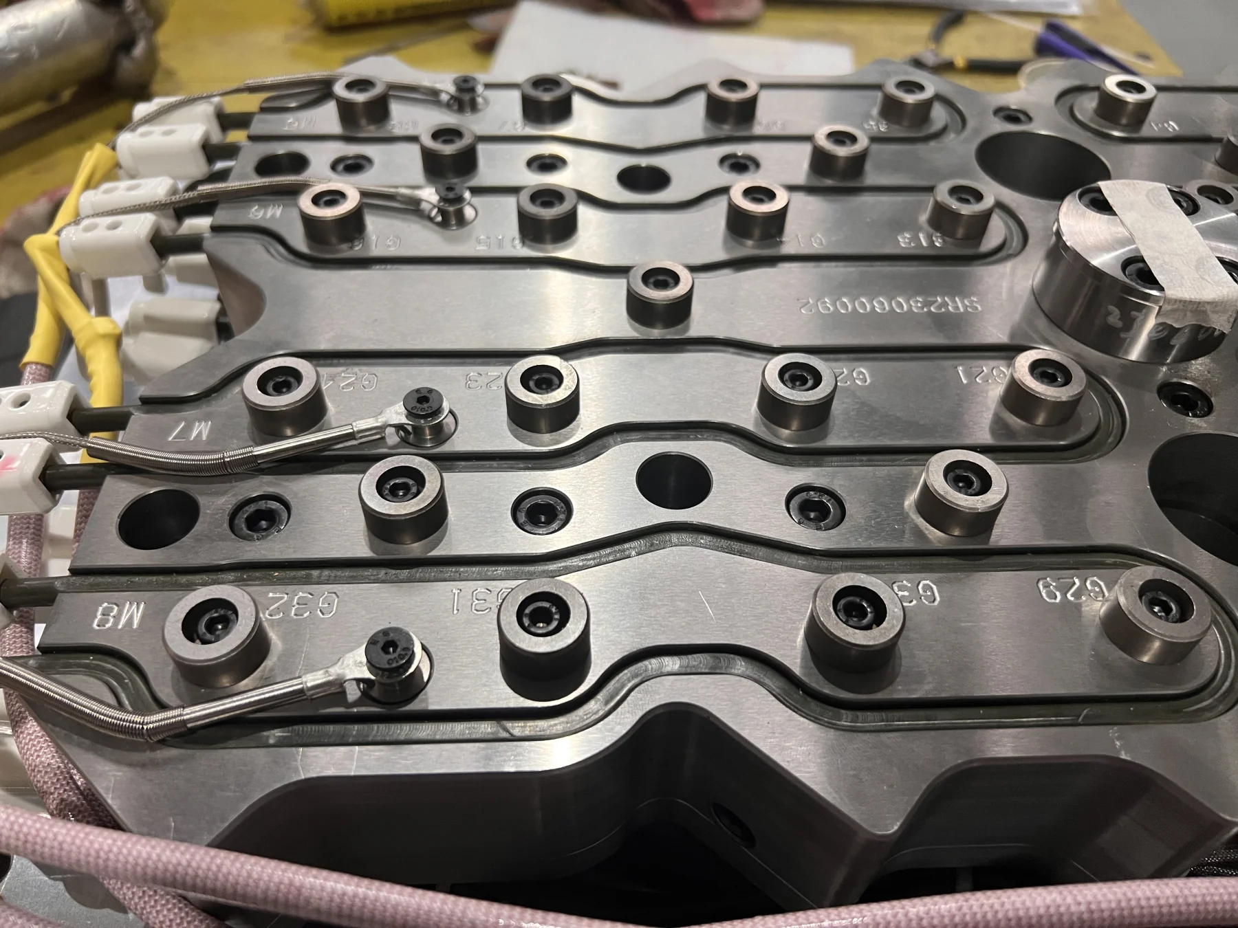
The available hot-runner component package uses HOTSET heaters from Germany with PCT nozzles and insulators from the United States.
Project specification
The proposal records runner type, valve-gate actuation, zones, controller, connectors and service parts.
 View image
 View image
 View image
Hot runner
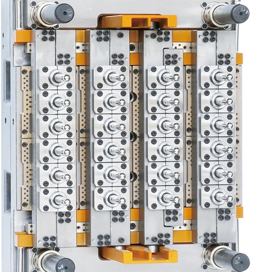
The hot-runner specification explains how the 24 drops are heated, controlled, actuated and maintained, including the zones, interfaces and service parts.
Flow review and channel sizing for the approved preform and PET material
Heating zones, thermocouples, connectors and controller capacity
Valve-gate actuation, cylinder location and sealing arrangement
Nozzle, heater, thermocouple and valve-component spare parts
Access method for cleaning, replacement and fault diagnosis
 View image
Cooling
Cooling claims only become useful when circuit layout and the buyer's actual water temperature, pressure, flow and quality are considered together.
Separate circuit identification for core, cavity and neck-ring areas
Required inlet temperature, pressure and flow stated for the project
Connection sizes, circuit map and cleaning or maintenance access
Trial record tied to the actual cooling-water condition
Cycle discussion based on part, resin, machine and cooling together
Machine and output
A 24-cavity mold can run on a suitable general-purpose injection platform when the exact injection unit, mold envelope, controls and utilities match the proposed mold.
Total shot, screw diameter, injection pressure and plasticizing capacity
Platen size, tie-bar spacing, mold height range and mounting pattern
Opening stroke, daylight, ejector or take-out clearance and handling method
Temperature zones, connectors, controller capacity and valve-gate actuation
Cooling-water temperature, pressure, flow, air, hydraulic and electrical interfaces
Approved preform, PET resin, verified cycle, operating hours and utilization target
Cavity feasibility
Cavity comparison
Enter weight and output
The result will show the cycle ceiling and part mass for 24, 32, 48, 64, 72 and 96 cavities. A specific recommendation appears only when a verified cycle is entered.
The comparison uses preform weight for part mass and a verified cycle for output selection. Wall thickness, geometry, PET resin, cooling water, hot runner, machine performance and quality requirements complete the engineering review.
24 versus 32 cavities
The extra eight cavities are useful only when they solve a real capacity requirement and the exact machine, runner, cooling and maintenance scope can support them.
| Decision factor | 24 cavities | 32 cavities | What to verify |
|---|---|---|---|
| Parts per cycle | 24 preforms | 32 preforms | At the same cycle and utilization, 32 cavities produces 33.3% more parts per cycle. |
| Part shot basis | 24 x approved preform weight | 32 x approved preform weight | Add the project process allowance and verify the exact injection unit for either option. |
| Mold and machine | 24-cavity envelope and interfaces | Larger cavity set to be checked | Match each option to its platen, mold height, opening and take-out requirements. |
| Runner and controls | 24-drop runner and control layout | 32-drop runner and control layout | Compare zones, actuation, spare parts, service access and total mold price together. |
| Selection trigger | Meets demand with operating margin | Extra capacity solves a proven demand gap | Choose from useful annual output and machine fit rather than cavity count alone. |
Trial and acceptance
The acceptance plan should connect the approved part to the exact trial machine and conditions, then review samples from all 24 cavities before packing.
01
Approve the preform drawing, neck finish, weight, PET grade and visible quality requirements.
02
Close the shot, platen, tie-bar, mold-height, control, utility and take-out checks before final design.
03
Run the mold on the agreed injection machine with the agreed PET resin, and record the machine, cooling-water condition, process settings and verified cycle.
04
Verify normal molding from all 24 cavities and supply one complete cavity-identified sample set for neck dimensions, weight, gate and appearance checks.
05
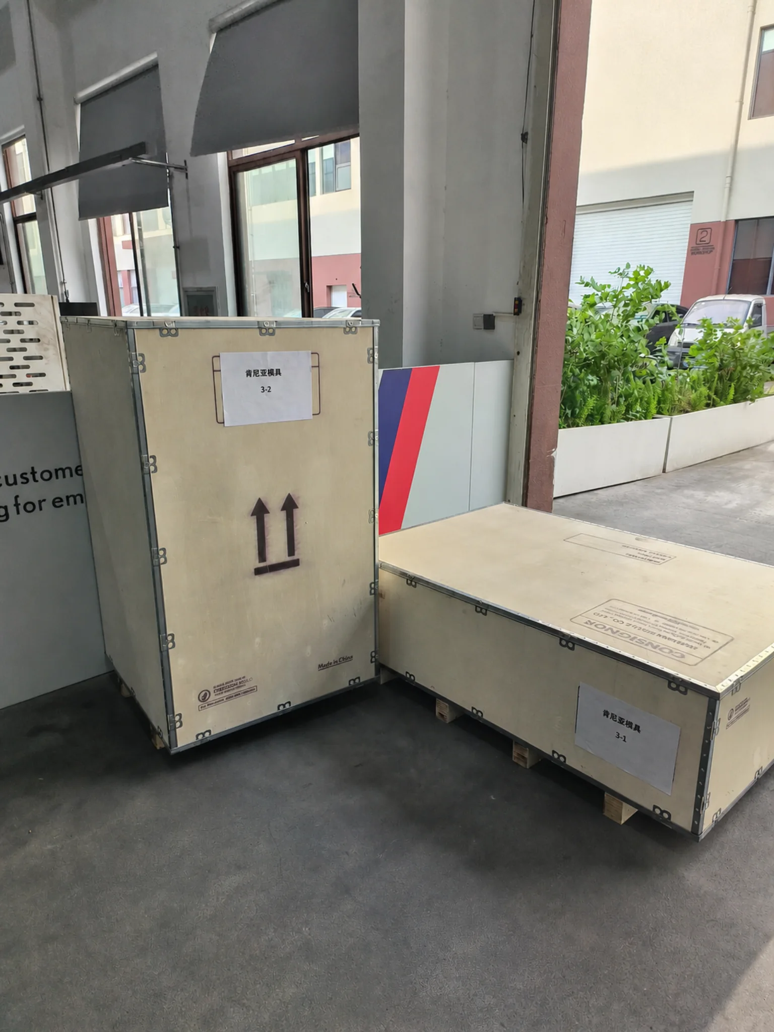
Provide the trial video and basic inspection records, complete bottle-blowing acceptance when required, then record samples, documents, spares, rust prevention and export packing.
Inspection evidence
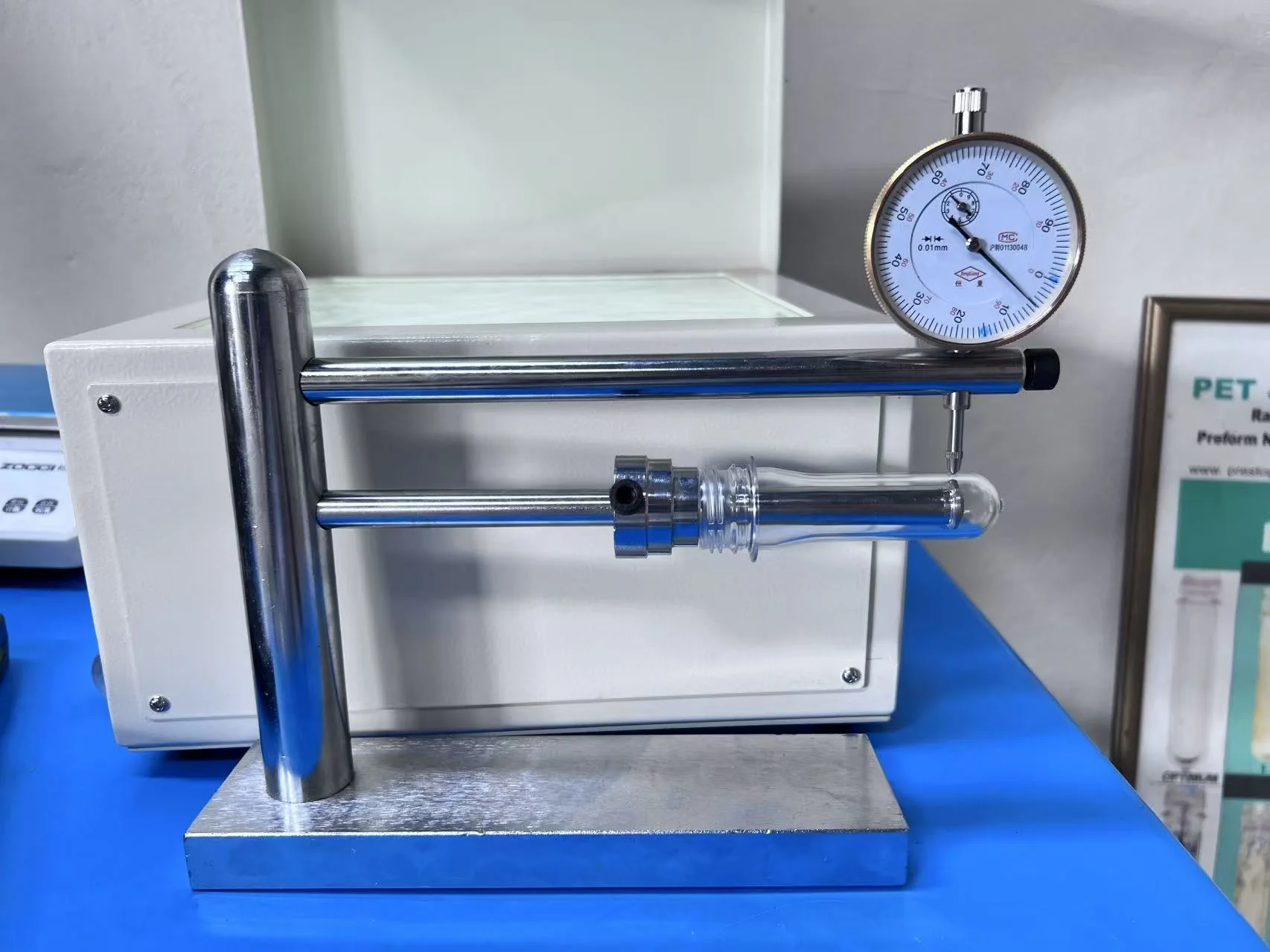
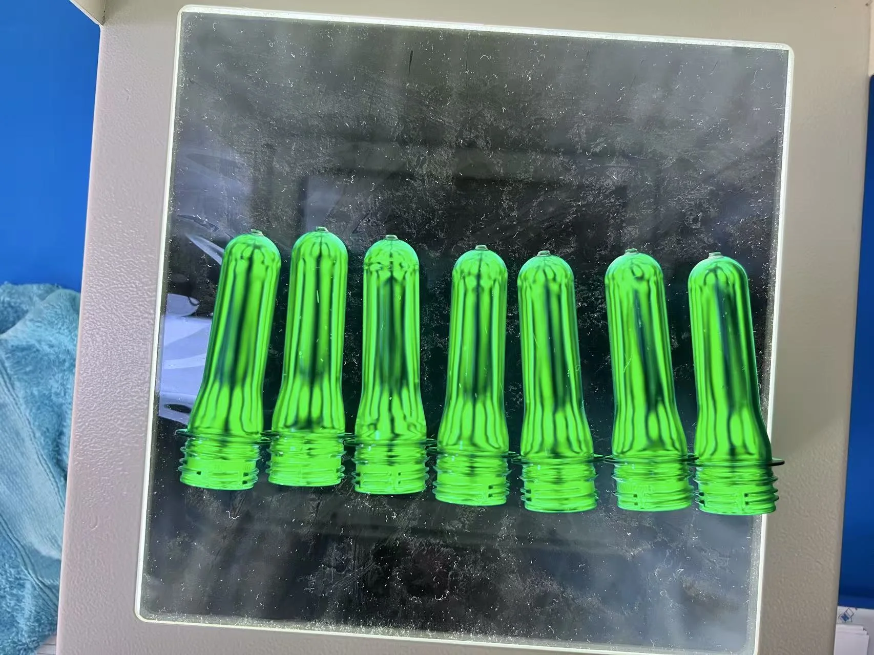
These photographs show practical sample checks. Final records link each result to the approved preform, trial condition and cavity identification.
 View image
 View image
 View image
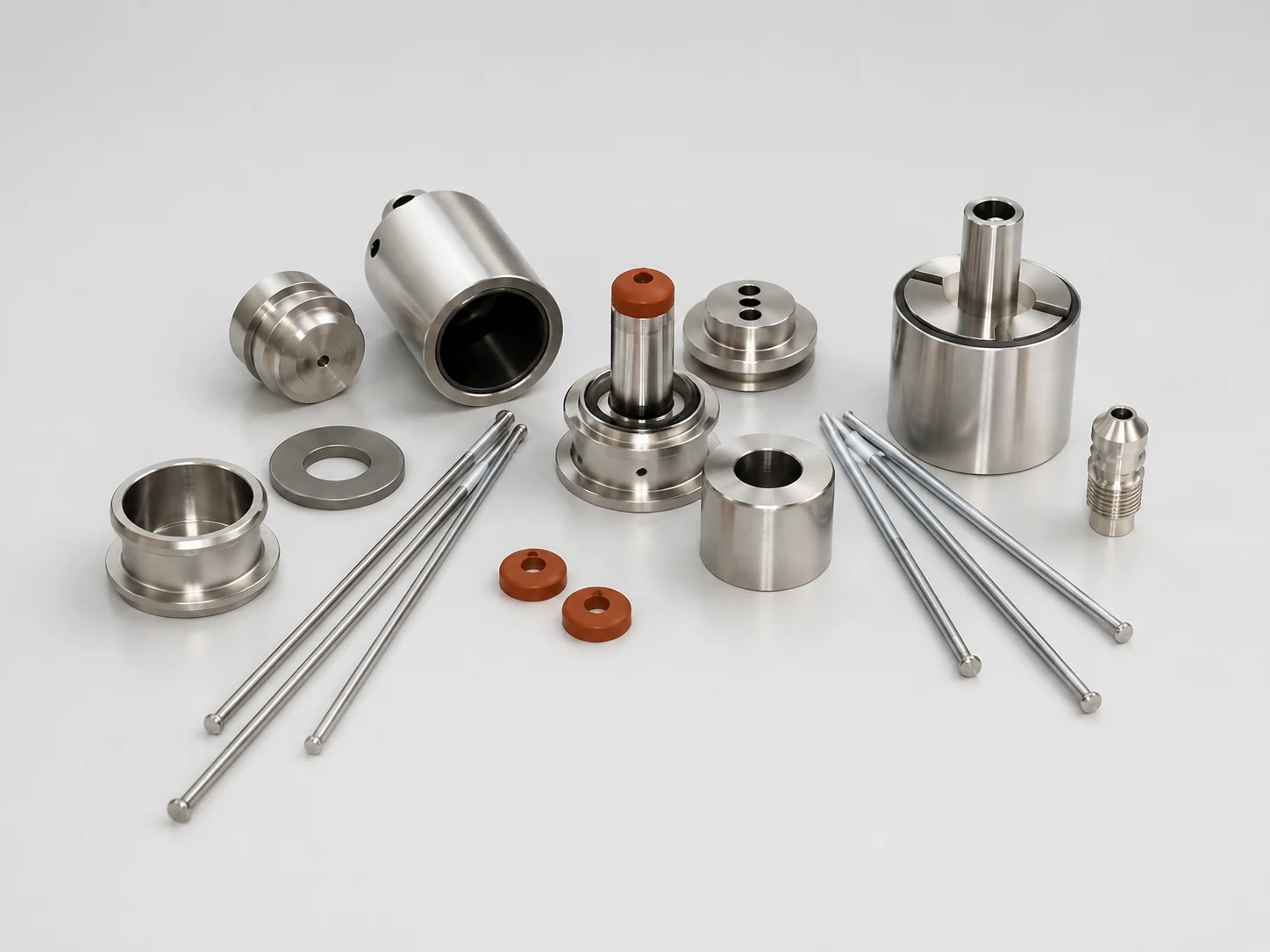
Quantities are based on the confirmed 24-cavity schedule derived from the supplied 48-cavity spare-parts list.
 View image
 View image
Enough to start the technical review
24-cavity RFQ
A drawing or clear sample, application and machine model provide a useful starting point for the first technical review.
Buyer questions
These answers set the review method. Exact project values remain tied to the approved drawing, machine and trial conditions.
Start with the preform drawing or sample, bottle application, neck finish, preform weight, PET resin, required output and injection machine model. Complete the remaining machine data during technical review.
A general-purpose platform can support the project when total shot, plasticizing capacity, tie-bar spacing, platen, mold height, opening, hot-runner controls, cooling and take-out match the proposed 24-cavity mold.
The confirmed water-bottle neck program includes PCO 1881, PCO 1810, 29/25 and 30/25. The approved preform and closure drawing decides the exact neck used in the project.
Use 24 multiplied by 3,600 and divide by the verified cycle in seconds, then multiply by expected utilization. Planned operating hours and days convert this into daily and annual output. Actual part, resin, machine, cooling and trial conditions establish the verified cycle.
Compare both when 24 cavities meets demand with little operating margin, when the exact machine may support 32 cavities, or when near-term growth makes the additional eight parts per cycle useful. Keep the preform, cycle and utilization basis identical in the comparison.
Run the mold on the agreed machine with the agreed PET resin, verify normal molding from all 24 cavities, identify a complete 24-piece sample set by cavity, inspect neck dimensions, weight, gate and appearance, provide the trial video and basic inspection records, and complete bottle-blowing acceptance when required.
Next decision