01
Controlled part input
Drawing revision, weight, resin, application, neck and closure are identified as approved or provisional.
PET preform mold design
Which design inputs must be fixed before a PET preform mold layout and quotation can be reviewed?
A PET preform mold design review connects the approved preform drawing, weight, PET resin and bottle application to the closure, cavity layout, hot-runner and valve-gate concept, cooling circuits, machine interfaces and acceptance plan. The page helps buyers and project teams identify which inputs are controlled, which remain assumptions and which evidence must close the review. Final geometry, tolerances, materials and operating values remain subject to the approved project drawings and commercial agreement.
Drawing, weight, resin and application
Neck, cavity and runner definition
Cooling, balance and machine fit
Trial and acceptance evidence
Enough information to start
Technical decision table
Keep the check, its reason and the resulting project decision visible in the same review. This prevents one keyword or one headline specification from replacing the technical basis.
| Decision factor | What to check | Why it changes the project |
|---|---|---|
| Preform definition | Controlled drawing and revision, target weight, resin, color or additives and bottle application | Establishes the molded part, total shot basis and inspection reference used by every later decision. |
| Neck and closure | Neck-finish drawing, cap or lid data, seal, tamper and downstream handling interfaces | Connects core and neck-ring geometry to the actual closure and line requirements. |
| Cavity architecture | Required output, candidate count, stack spacing, mold envelope, runner route and service access | Defines how the proposed layout fits the machine while remaining accessible for cooling and maintenance. |
| Thermal and runner systems | Hot-runner concept, valve-gate actuation, control zones, cooling circuits and plant-water conditions | Creates the working basis for fill balance, heat removal and process review across the cavity set. |
| Machine and acceptance | Injection unit, platen, tie bars, height, movement, controls, utilities, trial conditions and evidence | Links the proposed mold to an executable installation, trial and release plan. |
Project definition
Begin with the latest controlled preform drawing or an identified sample. Record the target weight, PET resin grade, color or additives, bottle application and the drawing revision used for quotation. These inputs define the part shot, visible requirements and the reference for later inspection. If any value is provisional, label it as an assumption and name who must approve the final value before the mold definition is released.
Use the complete neck-finish drawing together with the intended cap, pump or lid information. Review thread, sealing surface, tamper feature, support or transfer ring and downstream handling as one interface package. A familiar neck name identifies a family, but the controlled revision and actual closure establish compatibility and the neck-component acceptance checks.
Translate required saleable output into candidate cavity counts using the same approved preform and operating basis. Compare total shot, stack spacing, mold width and height, runner routing, cooling access and replaceable-component access for each candidate. The selected count is the supported layout that fits the intended machine and maintenance plan, not simply the largest number in a catalog.
The runner review identifies manifold and nozzle arrangement, heating and sensing zones, valve-gate actuation, connectors, controller responsibility and critical service parts. The proposal should show how the system relates to the cavity layout and approved preform. Trial records then provide the project-specific basis for reviewing gate condition and fill behavior without relying on an unsupported general performance promise.
Review cooling passages around the core, cavity and neck components together with inlet and outlet arrangement, circuit identification and the buyer's available water temperature, pressure and flow. Cycle discussion must state the resin, part, machine and utility conditions used. A drawing and recorded trial basis make cooling changes traceable when temperature or dimensional variation appears.
Plan how samples will be identified by cavity and compared for the agreed weight, gate, appearance and selected dimensions. The review should distinguish runner or process imbalance from isolated component or cooling issues. Acceptance sampling, measurement methods and decision limits come from the approved project specification rather than an invented universal tolerance.
Compare the proposed mold with the exact injection unit, total shot and plasticizing basis, platen and tie-bar space, mold-height range, opening movement, take-out clearance, hot-runner controls and plant utilities. Record adapters or buyer-supplied work in an interface schedule so the mold configuration and installation plan use the same machine data before order approval.
Define the trial machine, PET resin, approved drawing revision and recorded operating condition before samples are produced. Identify the required full-cavity sample set, measurement and visual checks, trial images or video, corrective-action record and shipment-release documents. The commercial agreement should state who performs each check and what evidence closes an open acceptance point.
Proposal scope
01
Drawing revision, weight, resin, application, neck and closure are identified as approved or provisional.
02
Cavity layout, component scope, runner, valve gate, cooling and service boundaries are stated.
03
Injection, envelope, movement, controls, utilities and buyer-supplied adaptations use the exact platform data.
04
Trial conditions, sample traceability, inspection methods, corrective actions and release documents are commercially assigned.
Evidence
Each image highlights a decision point in construction, component scope, service access or trial evidence. The project drawing, quotation and trial record then convert that review into an approved specification.
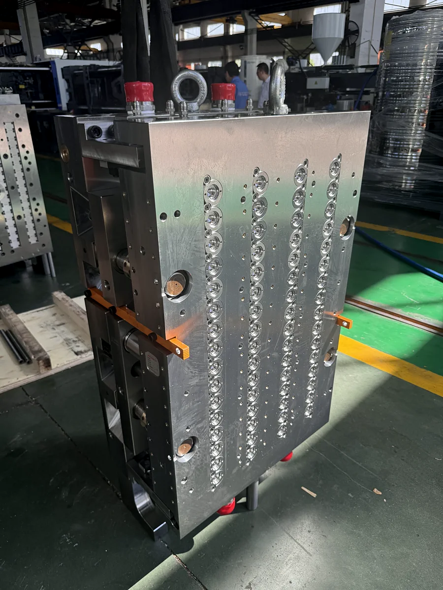
The photograph shows a real open multi-cavity PET preform mold. It supports discussion of cavity arrangement, alignment and service access; the approved project drawing controls the final layout and interfaces.
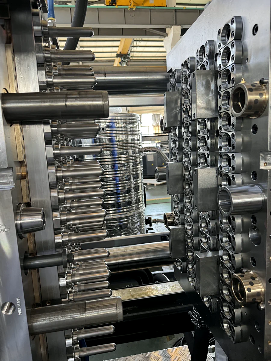
The close-up shows a real PET preform mold hot-runner manifold and associated components. Project documents define the final flow layout, heating zones, connections and service-parts scope.
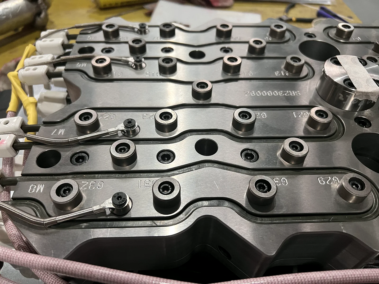
Real manifold, heater and sensor routing used for hot-runner scope review.
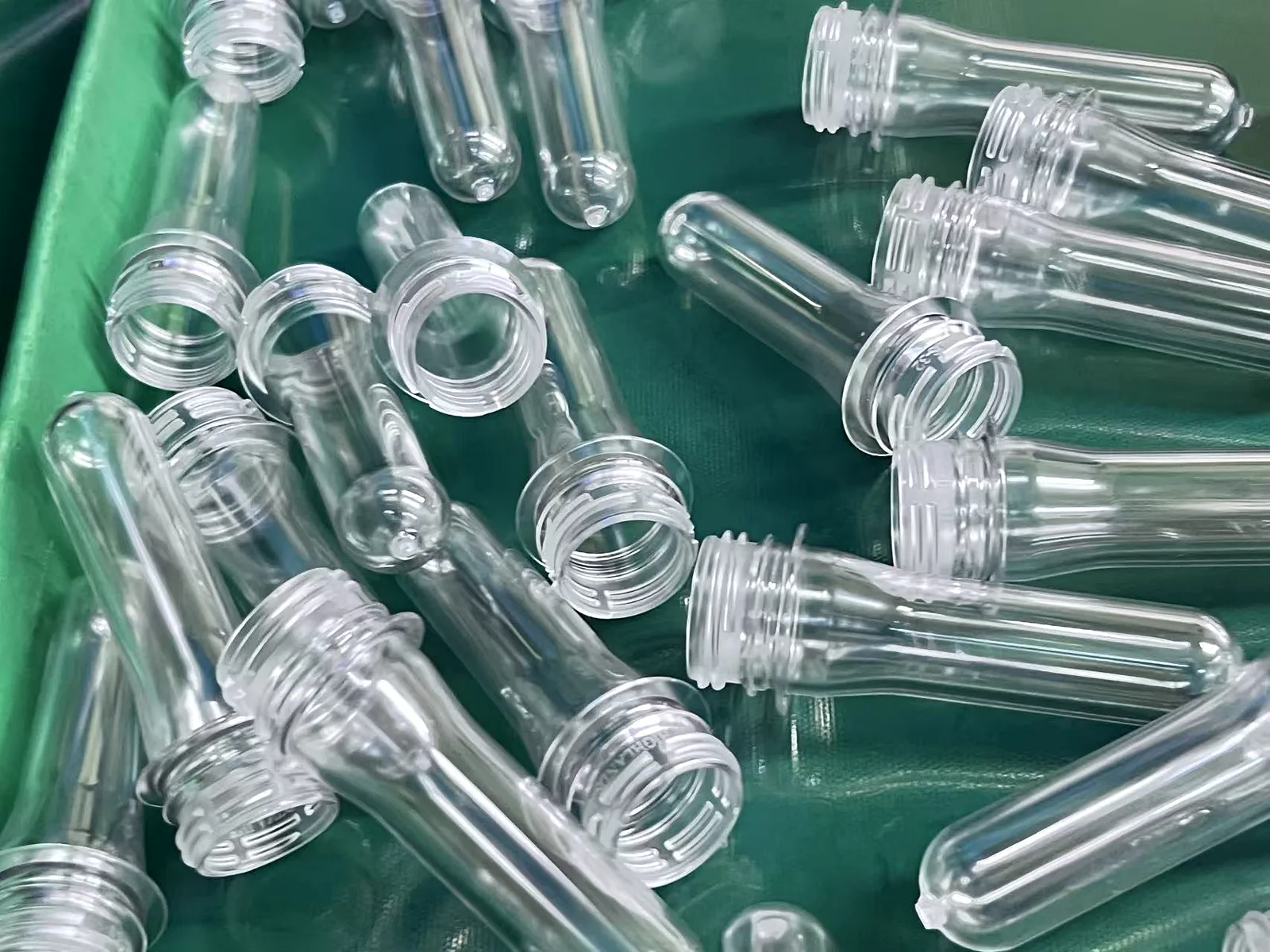
Trial samples retained for neck finish, gate, appearance and consistency checks.
Project controls
01
Changing weight, neck or closure after layout approval can alter shot, stack geometry, runner, cooling and acceptance scope.
02
A cycle figure is not comparable unless part, resin, machine, utilities and measurement point are recorded.
03
Mixed samples can hide local balance, cooling or component issues and weaken the acceptance record.
Page-specific RFQ
Send the information already controlled and identify what remains open. The first review organizes the part, mold system, machine interfaces and acceptance evidence into one design-input checklist for quotation.
Buyer questions
Fix or clearly label the preform drawing revision, weight, resin, bottle application, neck and closure, output target, candidate cavity count and exact machine information. Provisional items can remain open when the quotation states the assumption and approval owner.
Compare candidate counts using one approved preform and output basis, then check total shot, stack spacing, mold envelope, runner routing, cooling and service access against the exact injection platform.
Record circuit arrangement and identification, the components being cooled, connections and the available water temperature, pressure and flow. Link any cycle discussion to the stated part, resin, machine and utility conditions.
Use the approved drawing and trial basis, recorded machine and material conditions, cavity-identified samples, agreed weight, neck, gate, appearance and dimensional checks, corrective-action closure, component records and shipment-release documents.
Next decision
Core decision
Technical decision
Core decision
Technical decision
Core decision
Core decision